

Analogue Modular System A-


Width


HP

Depth


mm

Current

mA


Owners Manual


( Please contact first before visiting)

Octal Manual/Voltage Controlled Switches
The A-
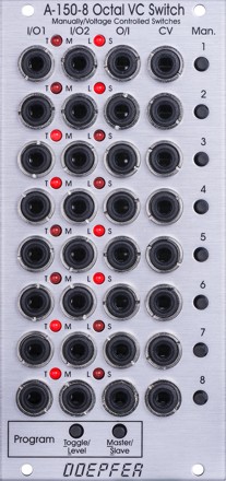
For each unit the operating mode can be selected: Toggle or Level controlled. In Toggle mode the rising edge of the CV input or operating the manual control button changes the state of the switch. In Level mode the switch state is defined by the voltage applied to the CV input (low voltage = I/O1, high voltage = I/O2) or by the state of the manual control button (not pressed = I/O1, pressed = I/O2). The modes are programmed very easily: Operating the Toggle/Level button of the program section displays the current state of each switch with the LEDs: left LED on = Toggle mode, right LED on = Level mode. Operating the manual control button of the switch in question changes the toggle/level mode while the Toggle/Level button of the program section is operated. During the programming possibly patched CV signals have to be removed as the CV signals would interfere with the manual operating buttons during the programming process.
In addition it's possible to define master/slave groups. In such a group the upper unit (= master) controls also the state of the following switches provided that they are defined as slaves. Master/slave programming is also very simple: Operating the Master/Slave button of the program section displays the current state of each switch with the LEDs: left LED on = Master, right LED on = Slave. Operating the manual control button of the switch in question changes the master/slave mode while the Master/Slave button of the program section is operated. During the programming possibly patched CV signals have to be removed as the CV signals would interfere with the manual operating buttons during the programming process.
When all 8 units are defined as master all switches are independent from each other. If for example the sequence is MSSSMSMS the control unit of the first switch also controls the switches 2, 3 and 4. The control unit of switch 5 also controls the switch 6, and the control unit of switch 7 also controls the switch 8. The current states of the slave switches are overwritten by the state of the master switch.
No manual
12
55
10HP
40
10HP
A-
